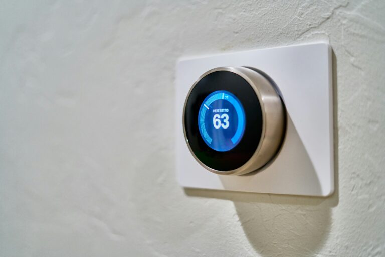

No. Thermostat wiring is driven by the HVAC system on the other side of the wall, not by the brand on the faceplate. Most homes use 24V low-voltage circuits, but electric baseboard heaters rely on 120V or 240V line-voltage wiring that behaves nothing like a standard setup. Wire count, terminal letters, and color conventions all shift with equipment type and system age.
What follows decodes the terminal letters, matches wire counts to specific systems, flags the C-wire issue that derails most smart thermostat upgrades, and walks through a quick compatibility check before you commit to a unit.
The Short Answer: Wiring Depends on the System, Not the Thermostat
A thermostat is a switch on the wall, sending a low-voltage signal to a furnace, air handler, or heat pump. The HVAC equipment decides how many conductors run to the wall and what each terminal does. Two homes with different heating systems can carry completely different bundles, even when both faceplates read Honeywell or Sensi.
Most residential setups use 24V low-voltage wiring because an indoor transformer steps household current down before it reaches the thermostat. A smaller number of homes, mostly those with electric baseboard or wall heaters, run line-voltage thermostats that switch 120V or 240V directly. These two worlds are not interchangeable, and crossing them can damage equipment or create a shock hazard.
Tip: Before you swap any thermostat, pull the faceplate and photograph the wire bundle. The letter at each terminal, not the wire color, tells you what your system actually does.
| System Type | Typical Wire Count | Common Terminals | Voltage |
|---|---|---|---|
| Heat-only furnace | 2 (sometimes 3) | R, W, optional G | 24V |
| Conventional heat + cool | 4 to 5 | R, W, Y, G, optional C | 24V |
| Heat pump (with aux) | 6 to 8 | R, W, Y, G, O/B, AUX, C | 24V |
| Millivolt gas fireplace | 2 | TH, TH (or TH-W) | <1V (self-powered) |
| Electric baseboard heater | 2 or 4 | L1, L2 (line-voltage) | 120V or 240V |
Decoding the Terminal Letters Behind the Faceplate
Each letter on the terminal block is shorthand for a function. Reading those letters turns a confusing nest of conductors into a map of what your system can do, and what the replacement thermostat must control.
The Core Five Terminals
- R terminal: Carries 24V power from the transformer back to the thermostat. Some systems split it into Rc (cooling) and Rh (heating) when two transformers feed the board.
- W terminal: Calls for heat. Energizing W closes a relay at the furnace and starts the burn cycle.
- Y terminal: Calls for cooling. Energizing Y engages the compressor contactor and indoor blower.
- G terminal: Activates the fan relay independently of heating or cooling, useful for continuous air circulation.
- C terminal: Provides the return path for continuous 24V power, the conductor most smart thermostats need to stay alive.
Heat Pump and Specialty Terminals
Conventional systems lack the extra terminals that heat pump setups require for reversing valve control and auxiliary heat. O/B controls the reversing valve that flips the unit between heating and cooling, while AUX or E energizes backup electric resistance heat when the pump cannot keep up. A second-stage terminal, often W2 or Y2, appears on multi-stage compressors or two-stage furnaces. Spotting these letters on the old faceplate is a strong signal you have a heat pump rather than a conventional furnace.
Those terminal clues matter most when you’re counting wires to figure out which HVAC family you’re actually dealing with.
Note: Wire color conventions exist, but they are not enforced by code. A white conductor might land on Y in one install and W in another. Trust the terminal label, never the insulation color.
How Wire Count Maps to HVAC System Type
Counting conductors in the thermostat cable is the fastest way to identify what sits on the other end. Each added function usually means one more conductor, so the bundle length is a rough fingerprint of the system.
Two-Wire and Three-Wire Setups
Finding only R and W on a two-wire bundle typically signals a heat-only system, such as a boiler or furnace where the fan is managed at the equipment rather than at the thermostat. Adding G brings the fan under thermostat control, a common layout in homes with a basic forced-air furnace and no central air. Three conductors can also describe a cool-only system where the letters are R, Y, and G.
Four-Wire and Five-Wire Setups
Four to five conductors is the standard configuration for a conventional system with both heating and cooling. R, W, Y, and G appear at minimum, with a fifth conductor present when a C-connection was added at install. Most homes built or rewired between 1990 and 2010 land in this range, and the count usually matches an 18/5 thermostat cable.
Six-Wire and Larger Bundles
Once the bundle climbs past six conductors, you are almost certainly looking at a heat pump system. The extras handle the reversing valve (O or B), auxiliary or emergency heat (AUX/E), and often a common return. Multi-stage equipment pushes the count higher. Eight conductors is common on a two-stage heat pump with a separate dehumidification signal.
Millivolt and Edge-Case Systems
Millivolt systems power themselves using the thermocouple inside a gas fireplace or some standing-pilot boilers. Because the equipment generates its own low-voltage signal, the wiring looks like a simple two-wire loop with no transformer and no C-wire. Many smart thermostats from Ecobee, Nest, and Honeywell explicitly exclude millivolt from their compatibility lists, so identifying this setup early prevents a return trip to the store.
That same compatibility gap is exactly where most smart-thermostat upgrades hit their first real wall.
The C-Wire Problem When Upgrading to a Smart Thermostat
Swapping an old analog thermostat for a smart one often runs into trouble with the common wire, better known as the C-wire. You are not adding a feature the old thermostat needed; you are supplying constant 24V power the new one requires to run Wi-Fi, a color screen, and onboard sensors.
Why Battery-Powered Models Got Away Without One
Analog thermostats used a mercury switch or a bimetallic strip and only drew current when closing a relay. Power came from the transformer during each call for heat or cool, and a pair of AA batteries handled the brief gaps between calls. A smart thermostat never fully powers down. It must stay awake to listen for app commands, run scheduling logic, and light the display.
How to Check for a Hidden C-Wire
Pull the faceplate and look behind the bundle. Many installers run a 5-conductor or 8-conductor cable through the wall but only land the conductors the original thermostat needed. A blue or brown wire tucked into the wall, not connected to any terminal, is often the unused C-wire. Verify by tracing it back to the furnace, where it should land on the C terminal of the indoor control board.
When No C-Wire Exists
Power Extender Kits (PEKs) solve the missing common wire without running new cable. The kit ships in the box with most Ecobee models and is available as an accessory for some Honeywell and Sensi units. It repurposes existing conductors to shuttle continuous power between the thermostat and the control board. The install takes about 20 minutes at the furnace end and avoids opening drywall.
Before pulling a new thermostat off the shelf, it’s worth pinning down whether your system even runs on that safer low-voltage kind.
Warning: Do not jumper Rc to C at the thermostat to steal power. It works on some systems and pops the transformer on others. Use a listed PEK or pull a new conductor.
Low-Voltage vs. Line-Voltage: A Safety Distinction That Gets Overlooked
Low-voltage and line-voltage thermostats live in separate electrical universes. A 24V thermostat acts like a remote control, sending a signal to a relay that handles the actual high-voltage switching. A line-voltage thermostat is the switch, carrying the full heating current through its own body and terminals.
Where Line-Voltage Shows Up
Electric baseboard heaters, in-wall fan-forced heaters, and some radiant ceiling systems use line-voltage thermostats because the install is simpler and cheaper on a per-room basis. The wire bundle is heavier, typically 12 or 14 AWG, and routes through a junction box rather than the low-voltage wall cavity used by HVAC control cable.
Why the Two Cannot Be Swapped
Putting a 24V smart thermostat on a 240V baseboard circuit will destroy the thermostat instantly and may trip the breaker or arc the wiring. Going the other way, installing a line-voltage thermostat on a low-voltage HVAC system, will not work because the relay coil never gets enough current to pull in. The mounting footprint also differs: low-voltage units attach to a small plastic plate, while line-voltage models anchor inside a metal electrical box.
| Feature | Low-Voltage (24V) | Line-Voltage (120V/240V) |
|---|---|---|
| Typical wire gauge | 18 AWG thermostat cable | 12 or 14 AWG building wire |
| Mounting | Plastic wall plate | Metal electrical box |
| Smart thermostat support | Yes (Ecobee, Nest, Sensi, Honeywell) | Limited (Mysa, Stelpro, some Honeywell) |
| Equipment controlled | Furnace, air handler, heat pump | Baseboard, wall heater, radiant ceiling |
Confirming Compatibility Before You Buy or Swap
A few minutes of inspection up front prevents a return, a service call, or a damaged control board. Treat the swap like a small diagnostic rather than a guess-and-pray job.
A Five-Step Pre-Install Checklist
- Photograph the current wiring: Remove the faceplate, take a clear shot of each conductor and its terminal, and leave the wires in place.
- Identify the system type: Check the furnace, air handler, or boiler label for voltage, fuel, and staging. Heat pump models usually say “heat pump” on the nameplate.
- Run a compatibility check: Most manufacturers, including Nest, Ecobee, Honeywell, and Sensi, host a free online tool that compares your photo to their supported configurations.
- Confirm a C-wire or PEK plan: If no C-wire is connected, decide whether to pull a new conductor, install a Power Extender Kit, or pick a smart thermostat that runs on battery-only modes.
- Verify the other end of the wire: Open the furnace panel and confirm the same letters appear at the control board terminals. A mismatch between thermostat-end and furnace-end labels is the root cause of most “nothing happens after install” calls.
Tip: Take the same photograph at the furnace end and the thermostat end. The labels must match, and that single check catches about 80% of miswires before the system is powered back up.
When to Call a Pro
Hire a licensed HVAC technician or electrician if the system is line-voltage, the existing wiring shows scorching or cracked insulation, the thermostat shares a circuit with an unfamiliar component, or the labels on the furnace board are unreadable. A service call typically runs less than the cost of replacing a fried thermostat or, worse, a control board that runs several hundred dollars.
Bottom Line
Thermostat wiring varies because HVAC systems vary. Count the conductors, read the terminal letters, and confirm a C-wire or PEK path before any smart upgrade. Match the thermostat to the equipment behind the wall, and the rest of the install becomes a 15-minute job instead of a guessing game.
FAQ
Do all thermostats use the same wiring?
No. Low-voltage HVAC thermostats share a common 24V terminal layout, but the wire count changes with the system, and line-voltage thermostats for baseboard heaters use a completely different 120V/240V wiring standard.
What color wires go on a thermostat?
Color conventions assign red to R, white to W, yellow to Y, green to G, and blue to C, but installers often diverge. Always confirm function at the terminal rather than trusting the insulation color.
Do I need a C-wire for my smart thermostat?
Most smart thermostats from Ecobee, Nest, Honeywell, and Sensi need continuous 24V power and work best with a C-wire. If no C-wire is present, a Power Extender Kit or a pulled conductor solves the issue.
Can I replace my old thermostat with any new one?
Only if the new thermostat supports the same system type and terminals. A battery-only conventional thermostat is a near-universal swap, while a heat pump or millivolt system narrows the compatible list dramatically.
How do I know what wires my thermostat needs?
Identify your system type, count the conductors in the wall, read the terminal letters on the existing faceplate, and run the manufacturer’s compatibility checker before buying.
Do smart thermostats require special wiring?
Smart thermostats require continuous 24V power, which almost always means a C-wire or a Power Extender Kit. A standard battery-only analog swap does not prepare the bundle for that demand.